


.jpg)
If you’re a licensed aircraft engineer, mechanic, or avionics technician, create your free AeroTechCareers profile to showcase your competencies and be found by recruiters actively searching for engineers like you.
Aircraft fault isolation: how engineers find the root cause behind multiple fault codes
Modern aircraft continuously monitor their engines, flight controls, electrical systems, navigation equipment and communications networks. When a system operates outside an expected range, the aircraft may record a fault and display a maintenance message.
Sometimes the message identifies a failed component. More often, several fault codes appear together.
This is where fault isolation begins.
The objective is not simply to replace the component named in the first message. Engineers must determine whether the aircraft has experienced several independent failures or whether multiple codes are symptoms of one underlying problem, such as a shared power supply, damaged wiring, incorrect software configuration, moisture intrusion or a failed data bus.
What is aircraft fault isolation?
Fault isolation is the structured process of identifying the most likely root cause of an aircraft fault and confirming it through approved tests.
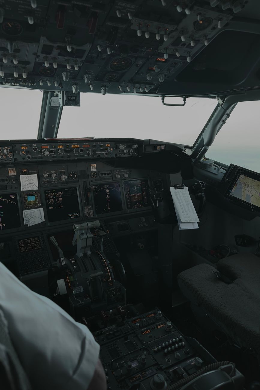
A fault may be a specific message recorded by an onboard computer. It can represent a confirmed failure, a suspected failure or a condition requiring further investigation. Faults may appear as cautions, warnings, maintenance advisories or equipment status indications.
Some messages are clear and specific. Others require interpretation and troubleshooting based on:
- The system involved
- The time and operating conditions
- Other faults recorded at the same time
- Recent maintenance or modification work
- Environmental factors such as moisture or corrosion
- The aircraft's wiring, power and data architecture
- The instructions in the approved maintenance data
The key principle is that a fault code is evidence, not automatically a diagnosis.

Where maintenance messages appear
Aircraft systems use built-in test equipment, commonly known as BITE, to monitor their own operation. BITE can detect abnormal signals, failed internal tests and communication problems between components.
Most BITE tests are performed at the front panel of the component, usually a line-replaceable unit, or LRU, in the electronic equipment bay. Some BITE tests are performed in the flight deck.
Front-panel maintenance messages may include:
- A specific light or group of lights
- An alphanumeric code
- A group of words or text, with or without an associated numeric code
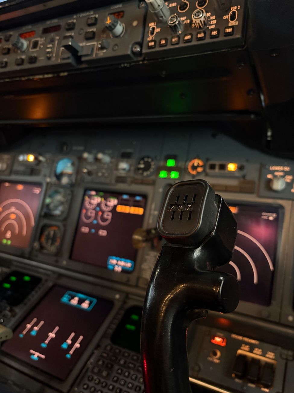
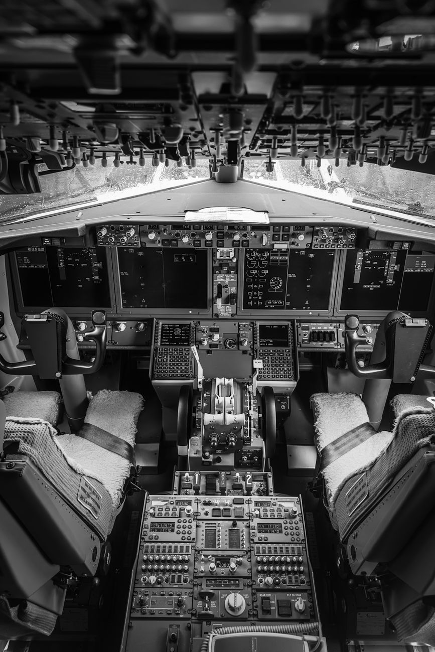
A maintenance message may also be presented through a control display unit, or CDU, in the flight deck. CDUs provide access to BITE information for several aircraft systems, allowing flight crew or maintenance personnel to retrieve recorded faults without directly accessing each LRU.
This creates several possible sources of information:
- Aircraft display systems, such as electronic flight instrument displays or central maintenance pages
- Control display units in the flight deck
- Front panels of LRUs in the electronic equipment bay
- Central maintenance computers or fault-reporting systems
- Maintenance records and previous troubleshooting reports
Engineers begin by establishing which messages were recorded, where they appeared and whether they refer to the same event.
Why multiple fault codes do not always mean multiple failures
Aircraft systems are highly interconnected. A single LRU may provide information to several other systems, while multiple components may depend on one electrical bus, data bus, circuit breaker or cooling system.

As a result, one failure can create a cascade of secondary messages.
For example, a loss of power to one avionics unit may generate:
- An internal equipment fault
- A communication failure
- A navigation data invalid message
- A downstream system caution
- A loss-of-redundancy indication
Replacing every component named in those messages could be expensive, ineffective and capable of introducing further defects.

Engineers therefore ask a more useful question: What do these messages have in common?
The answer may be a shared power source, common ground, wiring path, data bus, environmental condition or software configuration.
Step one: preserve the original evidence
Before resetting systems or clearing messages, engineers record the available evidence.
Important information can include:
- Exact fault wording and numeric codes
- The time and date of each message
- The aircraft's flight phase and operating conditions
- Whether the message was intermittent or persistent
- Which systems were affected
- Any associated cockpit indications
- Recent maintenance, component replacement or software loading
- Weather, temperature and humidity conditions
- Whether the aircraft had been exposed to water, salt air or a long period out of service
Fault data, work-order systems and troubleshooting manuals may exist in separate databases with limited synchronisation. This can make it difficult to see the complete history in one place. A careful maintenance record helps connect those sources. For practical guidance on recording maintenance experience, see how to fill out a CAP 741 logbook.
Clearing a fault before capturing its details can remove valuable evidence. A reset may temporarily restore normal operation while leaving the original cause unresolved.
Step two: find correlated maintenance messages
The next task is to identify messages that occurred together or followed a recognisable sequence.
This process is sometimes called fault correlation. Engineers compare:
- Common timestamps
- Shared systems or subsystems
- Identical or related fault descriptions
- The order in which messages appeared
- Faults recorded across different LRUs
- Whether messages disappeared or returned after a reset
- Whether the same fault occurred on previous flights
The first message in a sequence is not necessarily the root cause. It may be the first indication of a developing problem or simply the first system fast enough to report it.
A later message may be more useful if it identifies a loss of input power, failed reference signal or data-bus interruption.
Maintenance personnel also distinguish between primary faults and secondary faults. A primary fault directly reflects the initiating problem. A secondary fault is produced because another system has lost the information or service on which it depends.
Step three: understand the system architecture
Fault isolation becomes more effective when engineers map how the affected systems interact.

They may review:
- Wiring diagrams
- System schematics
- Power-distribution diagrams
- Data-bus architecture
- Connector and pin assignments
- Grounding and bonding arrangements
- Cooling-air paths
- LRU interfaces
- Redundancy and voting logic
Suppose three unrelated avionics units report communication failures at the same time. Rather than treating each LRU as an independent suspect, an engineer may look for a common data-bus segment, shared power feed or common connector.
Similarly, several units reporting low voltage may point towards a power-distribution problem rather than simultaneous internal failures.
The goal is to reduce a large collection of messages to a smaller list of possible common causes. Our guide to reading aircraft wiring diagrams for electrical fault finding explains how technicians can trace power and signal paths safely.
Step four: follow the approved maintenance data
Aircraft maintenance must be performed using the applicable, current and approved technical information. This may include the aircraft maintenance manual, fault isolation manual, wiring manual, component maintenance information and manufacturer service instructions. The aircraft maintenance manuals guide explains how these documents support troubleshooting and repair.
Regulatory guidance on continuing airworthiness is available from EASA's continuing airworthiness resources and the UK CAA's continuing airworthiness guidance.
The maintenance data normally provides a decision path:
- Confirm the fault
- Check whether related messages are present
- Inspect power, ground and signal inputs
- Perform specified BITE or operational tests
- Check wiring, connectors and bonding
- Substitute or replace equipment only when directed
- Repeat the test to confirm the corrective action
This sequence matters. It prevents unnecessary component replacement and ensures that troubleshooting is repeatable and traceable.
The equipment manufacturer's maintenance information is particularly important when inspecting avionics for environmental damage. FAA AC 43-206, Change 1, addresses corrosion inspection and prevention for avionics equipment and places manufacturer maintenance information first.
Moisture, contamination and corrosion are part of the logic
Environmental damage is not always visible from the flight deck.
Moisture, contamination and corrosion should be considered, particularly after:
- Fluid leaks
- Heavy rain or washing
- Coastal or salt-air exposure
- Condensation
- Long periods out of service
- Damage to seals, access panels or equipment-bay drainage
Corrosion can increase electrical resistance, damage connector contacts, weaken shielding or create intermittent connections. These defects may produce fault codes that appear unrelated because several circuits pass through the same area.
An inspection may therefore include the LRU, its connectors, backshells, mounting points, bonding straps and nearby wiring. Engineers follow the approved procedure rather than relying solely on visual appearance, since some electrical defects are not obvious until the circuit is tested under the specified conditions.
Step five: verify software, databases and configuration
Not every recurring fault is caused by hardware.
Aircraft systems depend on software, navigation databases, configuration files and equipment-specific settings. A component that is serviceable in isolation may generate a fault if it has:
- Incorrect software
- An outdated database
- An incompatible configuration
- A missing aircraft-specific parameter
- An incorrect part or modification standard
- A mismatch between redundant units
Configuration records are especially important after avionics upgrades, component changes or aircraft modifications. Engineers verify the installed standard against the aircraft records and approved instructions before concluding that an LRU has failed.

A software or configuration problem may also affect several systems simultaneously, making it resemble a wiring or network fault. For more on modern maintenance technology, read about aircraft maintenance in the digital age.
Step six: test the suspected root cause
A suspected cause must be confirmed through an approved test, inspection or replacement procedure.
Depending on the fault, this may involve:
- Repeating a BITE test
- Checking voltage or resistance at specified points
- Inspecting continuity and insulation
- Verifying data-bus signals
- Testing connectors and grounds
- Performing an operational check
- Installing a known-serviceable unit when authorised
- Monitoring whether the fault returns
A successful reset is not always proof of a permanent repair. Intermittent faults may disappear temporarily because vibration, temperature or connector movement has changed. See our guide to diagnosing intermittent avionics faults for further troubleshooting techniques.
The repair is confirmed when the prescribed test shows that the original fault has been corrected and no related fault remains.
The role of engineering judgement
Fault isolation combines technical documentation with experience.
A troubleshooting manual may identify the possible causes, but experienced engineers also recognise patterns:
- Several faults appearing after one maintenance event
- A problem that occurs only during climb or descent
- A message triggered by heat or vibration
- Repeated failures in the same aircraft zone
- A fault that disappears after movement of a panel or connector
- Multiple systems affected after a power interruption
This judgement does not replace approved procedures. It helps engineers choose the most logical path through them.
The best fault isolation is methodical rather than speculative. Engineers gather evidence, identify correlations, test the common points and document the result.
From fault code to a serviceable aircraft
Modern avionics can produce a large amount of maintenance data. That information is valuable, but only when it is interpreted in context.
A single fault code may identify a failed unit. Multiple codes require a broader view. Engineers must determine which messages are primary, which are secondary and which common condition could explain them all.

By combining BITE results, CDU and LRU messages, system diagrams, maintenance history, environmental inspections and approved troubleshooting procedures, maintenance teams can move beyond simply replacing parts.
They can identify why the aircraft reported the fault and confirm that the aircraft is safe and ready to return to service.




Login or register to join the conversation.
Join the discussion
0 comments