

.jpg)
If you’re a licensed aircraft engineer, mechanic, or avionics technician, create your free AeroTechCareers profile to showcase your competencies and be found by recruiters actively searching for engineers like you.
How to Read Aircraft Wiring Diagrams for Electrical Fault Finding
Wiring checks are a vital part of aircraft maintenance. Electrical faults can be difficult to locate, particularly when they are intermittent. For a practical introduction to inspection techniques, see our guide to aircraft wiring checks.
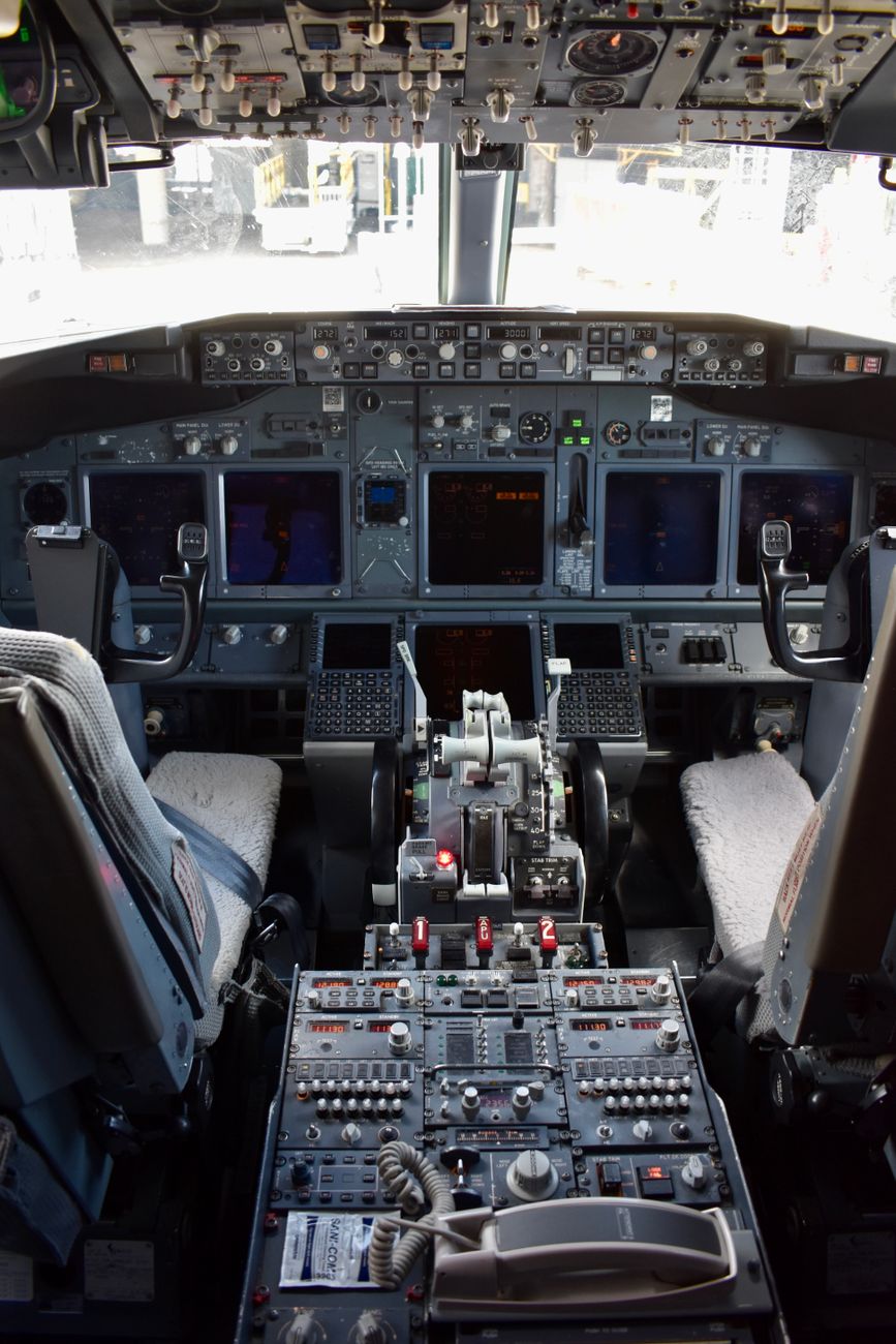
Whether you are investigating a flight control computer, diagnosing unexpected behaviour in a hydraulic power control unit or tracing a failed indication on a flight deck display, the wiring diagram provides a map of the system. Used correctly, it shows how power, signals and feedback move through the aircraft, and where that path may be interrupted.
Electrical fault finding must always be carried out using the approved aircraft maintenance manual, wiring manual, system description and applicable safety procedures. The aircraft documentation takes priority over any general guidance. Maintenance organisations should also consult the EASA continuing airworthiness requirements applicable to their work.
What is included in an aircraft wiring system?
Aircraft wiring forms part of the Electrical Wiring Interconnection System (EWIS). EWIS includes the wiring and associated hardware used to transmit electrical energy, data and signals between intended termination points.
This may include:
- Wires and cables
- Connectors and terminals
- Splices and termination devices
- Bus bars
- Bonding and grounding connections
- Shielding and screens
- Clamps, conduits and routing hardware
- Supports and protective sleeving
Wires do not carry electrical power alone. They also carry data, logic and feedback between avionics computers, flight controls, sensors, actuators and displays, often over considerable distances and through multiple connection points.
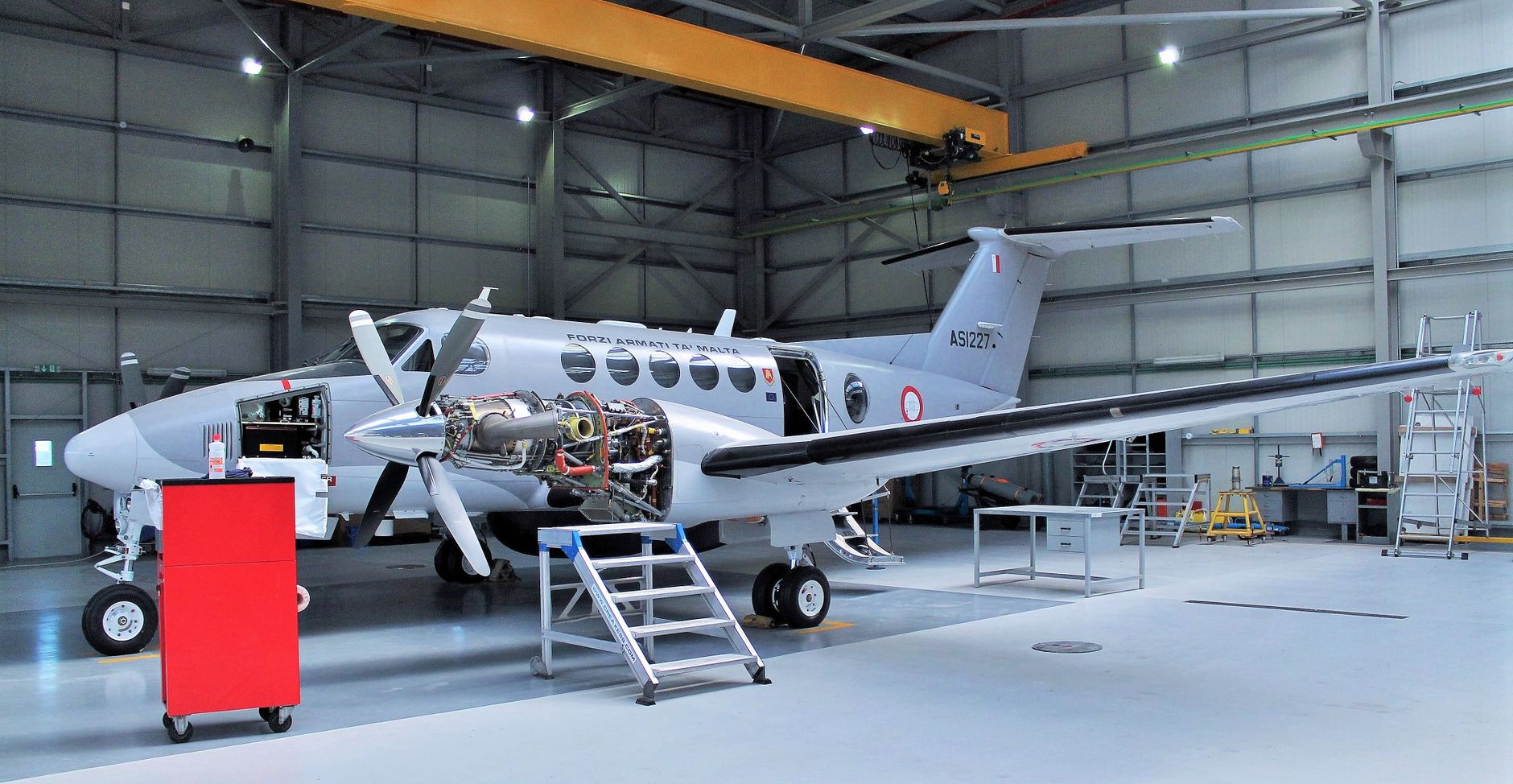
Aircraft wiring must operate in demanding conditions, including vibration, temperature changes, humidity and exposure to maintenance activity. Insulation may be Teflon-coated, fire-resistant or arc-track resistant, depending on the application. EWIS is used in almost every powered aircraft system, from flight deck displays and communications equipment to de-icing elements and flight control systems.
Under FAA 14 CFR Part 25, Subpart H, EWIS includes wires, wiring devices and combinations of these, including termination devices, installed to transmit electrical energy, data or signals. The requirements cover the installation and maintenance of related wiring, connectors, splices, bonding, shielding and support hardware so that they do not compromise airworthiness. The FAA's EWIS advisory guidance provides further context for wiring-system design and maintenance.
Start with the system, not the wire
A common mistake is to begin at the suspected wire and immediately test for continuity. A better approach is to understand the complete system first.
For example, consider the relationship between a laptop and a mouse:
- The laptop represents a flight control computer.
- The mouse represents a power control unit or other controlled component.
- The cable represents the aircraft wiring.
- Power travels from the laptop to operate the mouse.
- Feedback signals travel back to the laptop to report what is happening.
An aircraft system is more complicated, but the basic principle is similar. Before tracing individual conductors, identify:
- What supplies power?
- Which component receives the power?
- What signals or feedback are exchanged?
- What switching, protection or control devices are in the circuit?
- Where does the circuit return, through a dedicated wire, ground connection, structure bond or another system?
- What indications or fault messages should appear if the circuit operates correctly?
This system-level view helps prevent a wiring fault from being confused with a failed component or an incorrect system input.
Learn the layout of the wiring diagram
Aircraft wiring diagrams use symbols, references and conventions that may differ between manufacturers. Always consult the diagram legend and aircraft wiring manual before interpreting a circuit.
Most diagrams identify some or all of the following:
- Power sources and electrical buses
- Circuit breakers and fuses
- Relays and contactors
- Switches and control inputs
- Connectors and connector cavities
- Splices
- Ground points and bonding jumpers
- Shield terminations
- Wire numbers
- Wire sizes and types
- Pin or cavity assignments
- Component reference designators
- Junction boxes and terminal blocks
A diagram may be arranged by system function rather than physical location. Two components shown next to each other on the page may be installed many metres apart in the aircraft. Conversely, wires routed together physically may appear on different pages because they belong to different systems.

The diagram is therefore an electrical map, not necessarily an installation drawing.
Identify the intended current and signal paths
Trace the circuit in a logical direction. For a power circuit, begin at the source and follow the path to the load, then back to the return path.
A typical path might be:
Bus > circuit protection > relay or switch > connector > wire bundle > splice > component > ground or return
For a signal circuit, the path may be:
Sensor > connector > shielded cable > splice or terminal block > avionics computer > display or control output

Mark each point where the circuit can be interrupted. These points include:
- Circuit breakers
- Relays
- Switch contacts
- Connector pins
- Splices
- Terminal blocks
- Ground points
- Shield terminations
- Component input and output pins
This creates a list of possible fault locations rather than treating the entire wiring system as one continuous wire. A useful related case study is our report on relay replacement during an AOG fault.
Understand wire numbers and connector references
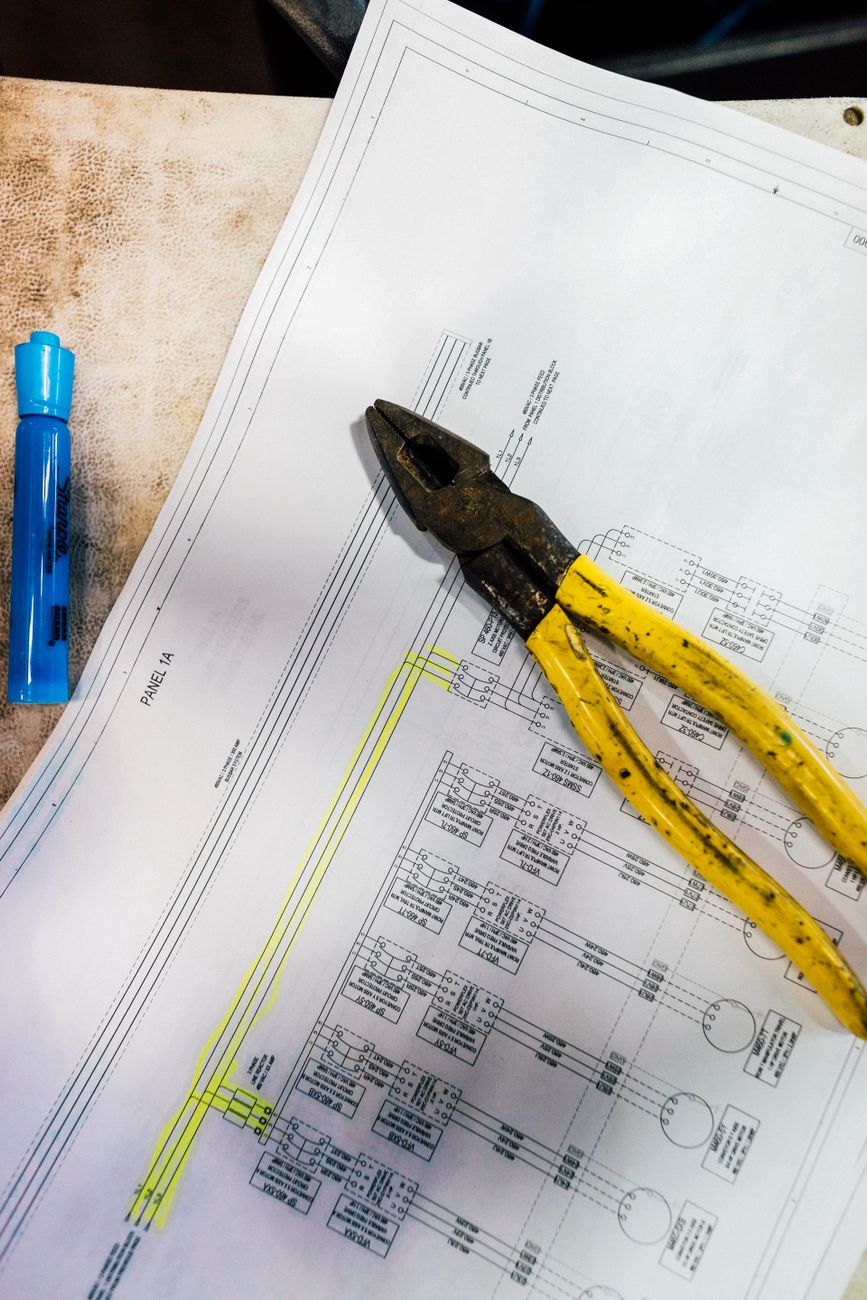
Wire identification is one of the most important skills in fault finding. A wire number normally identifies a conductor and may provide information about the circuit, destination or wire type. The exact format varies between aircraft.
Connector references are equally important. A diagram may show a connector by its identification number and identify individual contacts using pin or cavity numbers. The same wire may pass through several connectors before reaching its final termination.
When moving between diagram pages:
- Record the wire number.
- Record the connector identification.
- Note the pin or cavity number.
- Follow the continuation reference.
- Confirm that the destination matches the expected component or circuit.
Do not assume that wires with similar numbers are interchangeable. A small difference in a wire number, connector reference or pin designation may indicate a completely different circuit.

Trace the circuit from both ends
If a component is not receiving power, start by checking the expected supply at the component connector. If power is absent, work backwards through the circuit towards the source.
If the component has power but is not operating, check:
- The return or ground path
- Control inputs
- Feedback outputs
- Reference voltages
- Enable or interlock signals
- Communication lines
- The component's own built-in protection
Tracing from both ends can quickly narrow the problem:
- Correct voltage at the source but not at the load suggests an open circuit, high-resistance connection, failed relay or connector problem.
- No voltage at the source suggests a supply, protection or control problem.
- Correct power and return but no operation may point to the component or its control logic.
- Correct continuity but incorrect operation may indicate a high-resistance connection, insulation breakdown, short circuit, shielding problem or intermittent fault.
Do not confuse continuity with circuit health
A continuity check only shows that a measurable electrical path exists under the test conditions. It does not prove that the circuit will perform correctly under load.
A wire may show continuity and still have:
- A loose or damaged terminal
- Corrosion inside a connector
- An improperly crimped contact
- Broken strands carrying only a small portion of the current
- High resistance at a splice
- Insulation damage allowing leakage to another conductor
- An intermittent open circuit caused by vibration or movement
For this reason, voltage-drop testing under the correct operating conditions can be more informative than a simple resistance test. A poor connection may show nearly normal continuity with no load but develop a significant voltage drop when current flows.
Use only the test method, test equipment and limits specified by the approved maintenance data. Applying an incorrect voltage or resistance test to an avionics circuit can damage sensitive equipment.

Pay particular attention to connectors and terminals
Connectors are critical control points within EWIS. They provide removable connections between wiring harnesses, equipment, junction boxes and aircraft structure.
Common connector-related faults include:
- Poor contact engagement
- Bent, recessed or backed-out pins
- Incorrect contact installation
- Damaged or missing seals
- Moisture or contamination
- Corrosion
- Improper crimping
- Damaged backshells
- Excessive strain on the cable
- Inadequate shielding or bonding
A connector can appear secure while a terminal behind it is not fully locked in position. Similarly, an imperfect crimp may work during a static test and fail when exposed to vibration, thermal cycling or current load.
When the wiring diagram points towards a connector, identify the exact cavity and inspect it in accordance with the maintenance manual. Avoid unnecessary disturbance of connectors, since repeated disconnection can itself cause damage or contamination.
Follow splices, grounds and bonding paths
Splices are often hidden inside wire bundles or protected areas. They may join several wires, distribute power or combine signals. A splice that is open, corroded or mechanically damaged can affect more than one system function.
Grounds and bonds deserve the same attention as power conductors. A circuit may have the correct supply voltage but still fail because its return path has excessive resistance.

Check the diagram for:
- Dedicated ground wires
- Ground studs
- Structure returns
- Bonding jumpers
- Equipment case grounds
- Shield drain wires
- Common grounding points shared by multiple circuits
A poor ground can cause unreliable indications, fluctuating sensor values, communication errors or intermittent computer resets.
Use the diagram to investigate intermittent faults
Intermittent faults are often difficult to locate because the circuit may test correctly when the aircraft is stationary. The diagram helps identify areas that should be inspected in relation to movement, vibration and environmental exposure. For more on structured avionics troubleshooting, read how engineers diagnose intermittent avionics faults.

Areas of interest may include:
- Wire bundles near moving flight control surfaces
- Clamps and supports
- Pass-throughs and grommets
- Areas close to heat sources
- Locations exposed to moisture or fluid contamination
- Connector backshells
- Splices inside bundles
- Wiring disturbed during unrelated maintenance
- Sharp bends or excessive tension
- Places where wires contact structure or other equipment
On older aircraft, EWIS may have been designed according to a fit-and-forget approach. Over time, ageing, vibration, heat and contamination can cause deterioration. Inadvertent collateral damage during inspections, modifications or unrelated maintenance can also create faults that are difficult to see because the damage is inside a bundle or behind a connector.
Where approved procedures permit, carefully controlled movement, flexing, vibration simulation or temperature-related testing may help reproduce an intermittent fault. These actions must be performed within the limits of the maintenance data and without damaging the wiring.

For additional background on EWIS hazards and safe maintenance practice, consult the SKYbrary EWIS guidance.
Read shields and twisted pairs correctly
Some circuits require protection from electrical interference. The diagram may show:
- Shielded cables
- Twisted pairs
- Coaxial cables
- Shield drain wires
- Single-point or multi-point shield terminations
- Equipment case bonding
A shield is not always grounded at both ends. The correct termination depends on the system design. Connecting or disconnecting a shield incorrectly can introduce interference, communication faults or signal errors.
Maintaining the twist of a data pair and preserving the specified cable construction can also be essential to system performance. Do not repair, reroute or reterminate shielded or data wiring without following the approved instructions.
Compare the diagram with the physical installation
After tracing the electrical path on paper, compare it with the aircraft installation.
Look for:
- Wire numbers that do not match the diagram
- Unrecorded modifications
- Incorrect routing
- Missing or damaged clamps
- Chafing against structure
- Crushed or sharply bent cable
- Fluid contamination
- Heat damage
- Unsupported connectors
- Evidence of previous repairs
- Bundle separation or clearance issues
Aircraft may contain approved modifications, service bulletins or configuration differences that affect the wiring. Always confirm that the diagram applies to the aircraft registration, serial number and current configuration.

A practical fault-finding sequence
A structured process reduces unnecessary component replacement:
- Confirm the reported fault. Record when it occurs and whether it is constant or intermittent.
- Review the system description. Understand what the system is intended to do.
- Obtain the correct wiring diagram. Check aircraft effectivity and modification status.
- Identify the power, signal and return paths.
- Locate test points and expected values.
- Check circuit protection and power supplies.
- Measure at the component connector.
- Work backwards or forwards through each connection point.
- Inspect connectors, terminals, splices, grounds and routing hardware.
- Use voltage-drop, insulation or other tests only as specified by approved data.
- Repair the fault using the approved procedure.
- Carry out the required operational and independent inspections.
- Record the findings and corrective action.
The objective is not simply to find a broken wire. It is to establish why the circuit failed, confirm that the repair has restored the intended electrical path and ensure that the surrounding EWIS has not also been compromised.
New technologies and future fault detection
Improved inspection and diagnostic processes for aircraft EWIS are being developed, particularly for ageing aircraft. Conventional ground testing may not reproduce every intermittent fault, especially when the fault depends on vibration, temperature or operational conditions.

Research and emerging systems include live-wire monitoring capable of detecting some intermittent faults during operation, as well as Arc Fault Circuit Interrupter technology intended to provide additional protection when arcing occurs. These technologies do not replace approved maintenance procedures, but they may provide earlier warning of deterioration that is difficult to locate during routine inspections.
As digital tools become more common in maintenance, technicians can also explore our overview of aircraft maintenance in the digital age.
Final thoughts
An aircraft wiring diagram is more than a collection of lines and symbols. It represents how electrical power, data, control logic and feedback move through the aircraft.
By identifying the complete circuit, following wire and connector references carefully, checking the return path and considering the condition of the wider EWIS, technicians can approach electrical fault finding systematically. This is especially important for intermittent faults, where a connector, splice, ground, shield or damaged section of wire may be just as significant as the component showing the fault message.
Thorough wiring checks help maintain safe, reliable aircraft systems and reduce the risk of replacing serviceable equipment when the real problem lies in the electrical path connecting it.



Login or register to join the conversation.
Join the discussion
0 comments