


.jpg)
If you’re a licensed aircraft engineer, mechanic, or avionics technician, create your free AeroTechCareers profile to showcase your competencies and be found by recruiters actively searching for engineers like you.
Part-66 B2 Module 5 explained: Digital techniques and electronic instrument systems
Part-66 B2 Module 5 introduces the digital systems that connect, process, display and distribute information throughout a modern aircraft. It covers binary data, logic gates, computers, memory, data buses, electronic displays, fibre optics and integrated avionics systems.
The central concept is straightforward: aircraft sensors produce information, computers process it, data buses distribute it, and displays present it to the flight crew. Once this chain is understood, the module becomes far more manageable.
What is Part-66 B2 Module 5?
Part-66 Module 5 is titled Digital Techniques / Electronic Instrument Systems. It provides the digital and avionics knowledge required to understand the systems installed on modern aircraft. Candidates should confirm the applicable syllabus and licensing requirements in the current EASA Part-66 requirements or the relevant UK CAA guidance.
The module generally includes:
- Electronic instrument systems
- Numbering systems
- Logic circuits
- Data conversion
- Digital data buses
- Basic computers and processors
- Memory devices
- Integrated Modular Avionics (IMA)
- Fibre optics
- Electrostatic discharge (ESD)
- Software fundamentals
- Aircraft display systems
- Digital avionics such as FMS, IRS, GPS, TCAS and fly-by-wire interfaces
For a B2 engineer, this module underpins much of the practical work associated with aircraft communication, navigation, display and flight-control systems. It also connects closely with the Part-66 Module 13 B2 aircraft systems study guide.
Module 5 exam snapshot
The exact examination format depends on the competent authority and examination provider. Always check the current UK CAA aircraft maintenance engineer licensing guidance or EASA requirements. As a study reference, many Module 5 question banks and examination formats use the following structure:
- Question bank size: approximately 1,094 questions
- Syllabus sections: five
- Exam time: 50 minutes for B1 and B2
- Pass mark: 75 per cent
These figures describe a common revision-bank and examination format, not a substitute for checking the current official requirements. The time pressure is significant. You may have less than a minute per question, so you must be able to identify symbols, perform conversions and reject distractors quickly.
The Module 5 syllabus at a glance
5.1 Electronic instrument systems
This section examines cockpit systems that convert aircraft data into usable information for the crew. You should understand:
- EFIS architecture
- EADI and EHSI functions
- ECAM and EICAS displays
- Display symbology and colour conventions
- Data sources and signal paths
- System redundancy
- The relationship between sensors, computers, buses and displays
- Basic glass-cockpit layouts
5.2 Numbering systems
This is one of the foundations of digital electronics. You will need to work with:
- Decimal, binary, octal and hexadecimal
- Binary-coded decimal
- Signed and unsigned numbers
- Place values
- Basic arithmetic in different bases
Do not treat number conversion as a minor topic. Errors in base conversion are a common cause of lost marks in Module 5.

5.3 Data conversion and buses
This section explains how analogue aircraft information becomes digital data, how digital information is converted back into analogue signals, and how computers exchange data. Key areas include:
- Analogue-to-digital converters, or ADCs
- Digital-to-analogue converters, or DACs
- Sampling and quantisation
- Serial and parallel data
- ARINC 429
- ARINC 629
- MIL-STD-1553
- Data-bus terminology
- Transmission faults and data-integrity concepts
5.4 Basic computers and processors
This section covers the building blocks of avionics computers, including:
- Central processing units
- Microprocessors
- Memory devices
- RAM and ROM
- Input and output interfaces
- Internal computer buses
- Multiplexing
- Software and firmware
- Computer architecture
- Integrated Modular Avionics
5.5 Fibre optics, ESD and software
Modern aircraft increasingly use high-speed, lightweight data-transmission systems. You should understand:
- Light transmission
- Fibre-optic cable types
- Connectors and termination
- Bend-radius limitations
- Inspection and cleanliness
- Advantages over copper wiring
- Electrostatic-discharge precautions
- Software loading and configuration principles
Electronic instrument systems: the glass cockpit explained
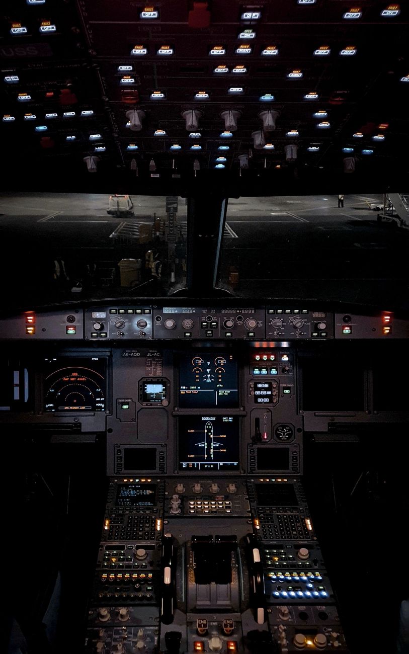
Older aircraft used separate electromechanical instruments for attitude, heading, airspeed, altitude and navigation. Modern aircraft combine much of this information on electronic displays.

This arrangement is generally referred to as an Electronic Flight Instrument System, or EFIS. A simplified glass-cockpit data flow is:
- Sensors measure aircraft parameters.
- Air-data and inertial computers process the measurements.
- Navigation and flight-management computers combine the information.
- Data buses distribute the information.
- Display computers format the data.
- Electronic displays present the information to the crew.
The display is therefore only the final part of a much larger system. When troubleshooting an incorrect indication, a B2 engineer must consider the complete chain rather than automatically blaming the display. The SKYbrary overview of EFIS provides useful additional context on electronic flight instrument systems.
EFIS
EFIS normally provides primary flight and navigation information on electronic displays. Depending on the aircraft, it may include:
- Attitude
- Airspeed
- Altitude
- Vertical speed
- Heading
- Course deviation
- Flight-director commands
- Radio altitude
- Terrain information
- Weather-radar information
- Traffic information
- Navigation waypoints
EFIS is not a single universal equipment design. The arrangement varies between aircraft types, but the principle remains the same: multiple data sources are selected, processed, monitored and displayed to support safe flight.

EADI: the attitude display
The Electronic Attitude Director Indicator, or EADI, is primarily associated with attitude and flight-director information. It commonly shows:
- Aircraft pitch and roll attitude
- Aircraft symbol
- Horizon and sky-and-ground presentation
- Flight-director bars or command cues
- Localiser and glideslope information
- Radio altitude
- Flight-mode annunciations
- Airspeed and altitude, depending on the display design
The EADI answers the question: how is the aircraft flying, and what guidance is being commanded?
Under examination conditions, associate the EADI with attitude, pitch and roll, flight-director commands, radio altitude, and vertical and lateral flight guidance. Although it may contain navigation-related information, its dominant function is attitude and guidance.

EHSI: the navigation display
The Electronic Horizontal Situation Indicator, or EHSI, presents horizontal navigation and situational information. It commonly includes:
- Compass rose or heading scale
- Selected course
- Bearing pointers
- VOR and ILS deviation information
- Waypoints and route information
- Weather-radar returns
- Traffic or terrain information
- Groundspeed and distance information
The EHSI answers the question: where is the aircraft going, and what is around it horizontally?
Associate the EHSI with navigation, compass or heading presentation, route and waypoint information, bearing and course guidance, weather radar, and horizontal situation awareness.

A useful memory aid is EADI equals attitude and EHSI equals horizontal situation. A pitch ladder, aircraft attitude, flight-director bars or radio altitude indicates the EADI. A compass rose, route, bearing or weather-radar display indicates the EHSI.
ECAM and EICAS
Two other important electronic display systems are ECAM and EICAS.
Electronic Centralised Aircraft Monitor, or ECAM, is commonly associated with Airbus aircraft. It presents engine parameters, aircraft system pages, warnings and cautions, system synoptics, procedures, crew actions and status information. ECAM is closely integrated with aircraft warning and system-monitoring computers. It does more than display a fault, it helps organise the information and present the appropriate response to the crew.

Engine Indicating and Crew Alerting System, or EICAS, is commonly associated with Boeing aircraft and other designs. It provides engine indications, warning and caution messages, advisory messages, system information and crew-alerting functions.
The precise implementation varies by aircraft, but the basic purpose is similar: centralise engine and aircraft-system information and present it electronically.
Display technology
Module 5 may also cover the characteristics of display technologies such as cathode-ray tubes, or CRTs, light-emitting diode displays, or LEDs, liquid-crystal displays, or LCDs, flat-panel displays, display processors and symbol generators.

You do not need to become a display designer. You should, however, understand the purpose of display electronics, how information is generated, and why a display fault may originate in the source computer, data bus, power supply or wiring. For a practical look at troubleshooting digital aircraft systems, see our guide to diagnosing intermittent avionics faults.
Numbering systems: binary, octal and hexadecimal
Aircraft computers process information in binary, while people generally work in decimal. Hexadecimal and octal provide convenient shorthand for groups of binary digits.
Binary
Binary uses only two digits, 0 and 1. Each position represents a power of two. For example:

101101 in binary equals 32 + 8 + 4 + 1, which equals 45 in decimal.
Octal
Octal uses the digits 0 to 7. Each octal digit represents three binary bits. For example, 57 in octal equals 5 × 8 + 7, which equals 47 in decimal.
Hexadecimal
Hexadecimal uses sixteen symbols:
- 0 to 9 represent decimal values 0 to 9.
- A represents 10.
- B represents 11.
- C represents 12.
- D represents 13.
- E represents 14.
- F represents 15.
Each hexadecimal digit represents four binary bits. For example, 2F in hexadecimal equals 2 × 16 + 15, which equals 47 in decimal.
One hexadecimal digit maps directly to four binary digits:
- 0 = 0000
- 5 = 0101
- A = 1010
- F = 1111
Avoiding base-conversion mistakes
Common errors include:
- Reading hexadecimal letters as decimal digits
- Using the wrong place value
- Forgetting that hexadecimal starts a new place at 16, not 10
- Misplacing a correctly converted part of a number
- Grouping binary digits incorrectly when converting to hexadecimal
- Failing to label the base while working
Write the base as a subscript and show the place values. This takes only a few seconds and prevents careless mistakes.

Logic gates and digital circuits
Logic gates are the basic decision-making elements of digital systems. They operate with binary inputs and produce binary outputs.
AND gate
An AND gate outputs 1 only when all inputs are 1.
OR gate
An OR gate outputs 1 when at least one input is 1.

NOT gate
A NOT gate reverses the input. An input of 0 produces an output of 1, while an input of 1 produces an output of 0.
NAND and NOR gates
A NAND gate is an AND gate followed by a NOT function. Its output is 0 only when all inputs are 1.
A NOR gate is an OR gate followed by a NOT function. Its output is 1 only when all inputs are 0.

NAND and NOR gates are known as universal gates. Complete logic systems can be constructed using only NAND gates or only NOR gates.
Do not simply memorise truth tables. Practise determining the output from circuit diagrams. Examination questions may combine several gates, add inverted inputs, or present the logic in an unfamiliar form.
Analogue-to-digital and digital-to-analogue conversion
Aircraft sensors often produce analogue signals, while computers process digital data. Conversion is therefore essential.

Analogue-to-digital conversion
An ADC converts a continuously varying analogue signal into a digital value. The process involves sampling the analogue signal, comparing the sample with discrete levels, assigning a binary value, and sending the result to a computer or data bus.
The sampling rate describes how often the analogue signal is measured. If it is too low, the digital system may not accurately represent a changing signal.
Resolution depends on the number of bits used by the converter. More bits provide more possible digital levels and finer measurement detail. An 8-bit converter has 256 possible levels, a 10-bit converter has 1,024, and a 12-bit converter has 4,096.

Digital-to-analogue conversion
A DAC performs the reverse operation. It converts a digital value into an analogue voltage, current or other continuously varying output.
Remember the direction:
- ADC: analogue to digital
- DAC: digital to analogue
Aircraft data buses
Data buses allow aircraft computers and equipment to exchange information without requiring a separate wire for every parameter. A B2 engineer must understand both the purpose of a bus and its practical limitations.
ARINC 429
ARINC 429 is one of the most widely recognised avionics data-bus standards. Its commonly associated characteristics include:
- Serial data transmission
- Point-to-point communication
- A single transmitter
- Multiple possible receivers
- Unidirectional data flow on a bus
- A defined word structure
- Label-based identification of transmitted data
- Twisted-pair wiring
- Common low- and high-speed transmission rates
Because ARINC 429 is generally unidirectional, return data requires another channel. Its word contains fields for items such as the data label, source or destination identification, data, sign or status information, and parity.
ARINC 629
ARINC 629 is a more complex aircraft data-bus standard that allows multiple terminals to communicate on a shared bus. Compared with ARINC 429, it supports a more capable multi-user arrangement, with controlled access, multiple transmitting and receiving terminals, and more complex communication management.

MIL-STD-1553
MIL-STD-1553 is associated with a controlled bus architecture involving a bus controller, remote terminals, data transfers managed by the controller, and redundancy and fault-tolerance features.
Be able to distinguish the general architectures of ARINC 429, ARINC 629 and MIL-STD-1553. Examination questions often test the relationship between transmitters, receivers, controllers and shared buses.
Computers, processors and memory
Aircraft computers follow the same broad principles as other digital computers, but are designed for safety, reliability, environmental resistance and predictable operation.

Basic computer structure
A basic computer includes a processor, input interfaces, output interfaces, memory, internal data paths, power supplies, and software or firmware.
The processor executes instructions and performs calculations. Input interfaces receive data from sensors or other systems. Output interfaces send commands or processed information to displays, actuators and other computers.
RAM and ROM
Random Access Memory, or RAM, is generally used for temporary storage while a computer is operating. Its contents may be lost when power is removed.

Read-Only Memory, or ROM, stores information that remains available without normal write access. It may contain fixed programmes or data.
You may also encounter programmable, erasable and electrically erasable memory devices. Understand the general purpose of each type and whether it is volatile or non-volatile.
Multiplexing
Multiplexing allows multiple signals to share a communication path. A multiplexer selects one of several inputs and connects it to a single output. The reverse process, demultiplexing, distributes a combined signal to the appropriate outputs.

Multiplexing helps reduce wiring weight and complexity, both of which are important on aircraft.
Integrated Modular Avionics
Integrated Modular Avionics, or IMA, uses shared computing resources and common modules to support multiple aircraft functions. It can provide:
- Shared processing
- Common cabinets or modules
- Resource partitioning
- Reduced equipment weight
- Simplified wiring
- Easier system integration
Shared resources also increase the importance of configuration control, software integrity, partitioning and fault isolation.

Fibre optics and ESD precautions
Fibre optics
Fibre-optic systems transmit information using pulses of light rather than electrical signals. Their advantages include low weight, high bandwidth, immunity to electromagnetic interference, electrical isolation, and potentially low signal loss over suitable distances.
Fibre-optic cables can be damaged by excessive bending, contamination, poor termination, scratched or damaged end faces, incorrect connector handling, pulling and crushing.
Always observe the specified minimum bend radius. Keep fibre-optic connectors clean and capped when disconnected. Even a small amount of contamination can significantly affect optical transmission.

Electrostatic discharge
Electrostatic discharge can damage sensitive electronic components without producing any visible sign of damage. Good ESD practice includes:
- Using approved wrist straps and grounding equipment
- Working on an ESD-protected surface
- Keeping components in approved protective packaging
- Avoiding unnecessary contact with connector pins
- Following aircraft-maintenance manual precautions
- Checking the condition of ESD equipment
An ESD-damaged component may fail immediately or develop an intermittent fault later. Both outcomes are unacceptable in an aircraft system.
Digital systems connected to Module 5
Flight Management System
The FMS combines navigation data, aircraft performance information, flight-plan data, and inputs from systems such as GPS and IRS. It provides guidance and navigation information to other aircraft systems and displays.

Inertial Reference System
The IRS uses inertial sensors to calculate aircraft attitude, position, velocity and heading. Its outputs may be distributed to flight displays, navigation computers and flight-control systems.
Global Positioning System
The GPS provides accurate position and timing information. Its data may be combined with IRS and other navigation sources to improve navigation performance and monitoring.
Traffic Collision Avoidance System
The TCAS receives and processes traffic information, then presents traffic indications and, where appropriate, resolution advisories to the flight crew.

Fly-by-wire
In a fly-by-wire aircraft, pilot control inputs are converted into electrical signals. Flight-control computers process those inputs and command actuators. The arrangement depends heavily on computers, data buses, redundant power supplies, multiple sensors, software, monitoring and fault-detection logic, and electronic displays.
For a B2 engineer, understanding this digital flow is essential when interpreting system tests and fault messages. You can also explore the practical impact of modern diagnostic tools in Aircraft Maintenance in the Digital Age.
Topics candidates often miss
Confusing the EADI and EHSI
Associate the EADI with attitude and flight guidance, including pitch, roll, the flight director and radio altitude. Associate the EHSI with navigation and horizontal situation information, including the compass rose, heading, route, bearings and weather radar.

Question wording may be deliberately indirect. Look for the information being displayed rather than relying solely on the instrument name.
Making base-conversion errors
Write down the place values and check the result using reverse conversion where practical. Remember that A equals 10, B equals 11, C equals 12, D equals 13, E equals 14, and F equals 15 in hexadecimal.
Confusing ADC and DAC
Attach the direction to the abbreviation: A to D equals ADC and D to A equals DAC. A sensor output may require ADC before computer processing, while a computer command may require DAC before controlling analogue equipment.

Memorising buses without understanding them
Ask whether the bus is unidirectional or bidirectional, whether it has one transmitter or several, whether multiple terminals share the medium, how data is identified, how access is controlled, and what the word or message structure contains.
How to study Module 5 effectively
Build a comparison sheet
Include quick comparisons for EADI and EHSI, ECAM and EICAS, ADC and DAC, RAM and ROM, serial and parallel data, ARINC 429 and ARINC 629, binary and hexadecimal, and fibre optics and copper conductors.
Practise conversions by hand
Practise decimal to binary, binary to decimal, decimal to hexadecimal, hexadecimal to decimal, binary to hexadecimal, and octal to binary conversions. The aim is to make the process automatic before the examination.

Draw the data flow
For each major system, sketch a simple diagram: sensor → computer → data bus → display. Add redundancy, monitoring and connected systems. This helps explain why a displayed value may be affected by several items of equipment.
Use question banks properly
Do not simply memorise answers. For every question, ask what principle is being tested, why the correct answer is correct, why the other options are wrong, and whether the answer would change if the wording changed.
Questions with worked explanations grounded in the Part-66 syllabus are more useful than questions that encourage recognition of familiar wording.

Practise under time pressure
If the examination gives you 50 minutes, practise completing mock tests within that limit:
- Answer straightforward questions first.
- Mark questions involving lengthy calculations.
- Return to uncertain questions later.
- Check units, bases and the direction of conversion.
- Do not spend several minutes on one question.
Final thoughts
Part-66 B2 Module 5 is the foundation for understanding the digital aircraft. It begins with binary numbers and logic gates, then progresses to processors, memory, data conversion, avionics buses, electronic displays and integrated systems such as EFIS, ECAM, EICAS, FMS, IRS, GPS, TCAS and fly-by-wire.
The module is broad, but its subjects are connected. Aircraft information is sensed, converted, processed, transmitted, monitored and displayed. Become comfortable with that process, distinguish the EADI from the EHSI under pressure, and take base conversions seriously. Consistent practice and genuine understanding will make Module 5 a manageable and valuable step towards a B2 licence.




Login or register to join the conversation.
Join the discussion
0 comments