

.jpg)
If you’re a licensed aircraft engineer, mechanic, or avionics technician, create your free AeroTechCareers profile to showcase your competencies and be found by recruiters actively searching for engineers like you.
How to troubleshoot intermittent aircraft electrical faults
Wiring checks are a vital part of aircraft maintenance. Electrical faults can be difficult to locate, particularly when they occur intermittently and disappear before a technician can reproduce them.
Whether the problem affects a flight control computer, an engine indication system or a hydraulic power control unit, a structured troubleshooting process helps identify the underlying cause. It also reduces the risk of replacing serviceable components while leaving the wiring defect in the aircraft. For a practical introduction to detailed wiring inspections, see our step-by-step guide to aircraft wiring checks.
A useful analogy is a mouse connected to a laptop. The mouse represents a power control unit (PCU), while the laptop represents the flight control computer. The laptop supplies power to the mouse, and the mouse sends feedback data to the laptop. If the cable is damaged, the mouse may work normally until the cable is moved. Aircraft wiring behaves in the same way. A circuit may pass a stationary test but fail during vibration, temperature changes or normal aircraft movement.
Why intermittent electrical faults are difficult to find
A permanent open circuit or short circuit is usually relatively straightforward to locate. An intermittent fault is more difficult because the circuit may return to normal before testing begins.
The defect may only appear under specific conditions, including:
- Vibration or turbulence
- Temperature cycling
- Moisture or fluid contamination
- Electrical loading or power switching
- Movement of a flight control surface
- Landing gear or flap operation
- Engine operation
- Mechanical loading of a connector or harness
- Maintenance activity near the affected wiring
Aircraft wiring is exposed to several degradation mechanisms during its service life. Insulation can become brittle, conductors can break, and connectors can loosen or corrode. Wiring can also be damaged by chafing, incorrect clamping, excessive bending or contact with the aircraft structure.
Statistical data commonly associated with ageing-aircraft electrical wiring identifies insulation damage as the most frequent fault type, accounting for approximately 37% of faults. Conductor breaks account for about 11%, while connector failures account for approximately 9%. These defects are often hidden within the aircraft structure, which makes them harder to see and test.
Human interaction is another important factor. NASA has reported that as many as 80% of wiring faults may be associated with human interaction, including maintenance activity. A wire may be disturbed, incorrectly routed, over-tightened, inadequately supported or damaged by nearby work, even when the original task did not involve the electrical system.
The FAA provides additional guidance on aircraft wiring and electrical installation practices in its EWIS resources. Always apply the aircraft manufacturer's approved maintenance data before carrying out an inspection or repair.
Start with the aircraft records
Before touching the aircraft, review all available information. The fault history may provide clues that are not obvious from the current cockpit indication.
Check the following:
- The exact fault message or fault code. Record the wording, code and associated system. Small differences in a message can indicate that the fault has moved from a sensor circuit to a data-processing or wiring problem.
- When the fault occurs. Determine whether it appears during a particular phase of flight, after engine start, during flap movement, in wet weather or after a maintenance task.
- The fault history. Look for repeated fault codes, apparently unrelated messages or faults affecting several systems in the same area.
- Previous maintenance actions. Note which line-replaceable units, connectors, circuit breakers or harnesses have already been inspected or replaced.
- Aircraft configuration and modification history. Wiring may have been altered by service bulletins, repairs, supplemental type certificates or previous troubleshooting.
- Applicable maintenance data. Use the aircraft maintenance manual, wiring diagram manual, fault isolation manual, standard wiring practices and any relevant airworthiness directives or service information.
A fault that changes after a component replacement should not automatically be considered fixed. For example, a new fault code may indicate that the original defect remains but is now being detected at a different point in the system.
Confirm the reported fault
The first objective is to establish whether the reported fault can be reproduced. Follow the approved maintenance procedure and record the aircraft configuration during the test.

If the fault does not appear, do not assume that the report was incorrect. Intermittent faults often disappear when the aircraft is stationary or when the wiring is no longer exposed to the conditions that caused the problem.
Where approved procedures permit, compare the following:
- Normal and abnormal system indications
- Fault codes before and after a system reset
- Signals at the source and at the receiving computer
- Continuity and insulation resistance under different conditions
- The affected circuit with a similar, known-serviceable circuit
Every test must be performed with approved equipment, limits and procedures. Aircraft electrical systems can be damaged by incorrect test voltages, unsuitable meters or improper backfeeding of circuits.
For related diagnostic methods, read our guide to how engineers diagnose intermittent avionics faults.
Divide the system into sections
Avoid treating the entire system as one large circuit. Break it into manageable sections:
- Power supply
- Circuit protection
- Sensor or switch
- Local wiring
- Connector interfaces
- Data bus or signal conditioning
- Receiving computer
- Indication or control output
This approach helps determine whether the fault is caused by a component, the wiring between components or a power or ground problem.
For example, if a flight control computer reports an unexpected discrete input, begin by verifying the input at the computer connector. Then work backwards through the harness to the associated switch, sensor or PCU. If the signal is correct at the source but incorrect at the computer, the intervening wiring or connector becomes the primary area of investigation.
Inspect connectors carefully
Connectors are a common source of intermittent faults. A connector may appear correctly installed while still containing a loose, damaged or poorly crimped contact.
Inspect for:
- Backed-out pins or sockets
- Bent, spread or damaged contacts
- Corrosion or moisture
- Contamination from fluids or dirt
- Broken connector locks
- Damaged backshells
- Poor strain relief
- Incorrectly positioned seals
- Evidence of arcing or overheating
- Wires that move excessively at the rear of the connector
Do not rely on visual inspection alone. A contact may pass a basic continuity check but fail when subjected to vibration or a small change in position. Follow the applicable connector inspection and contact-retention procedures, including the correct use of gauges and test equipment.
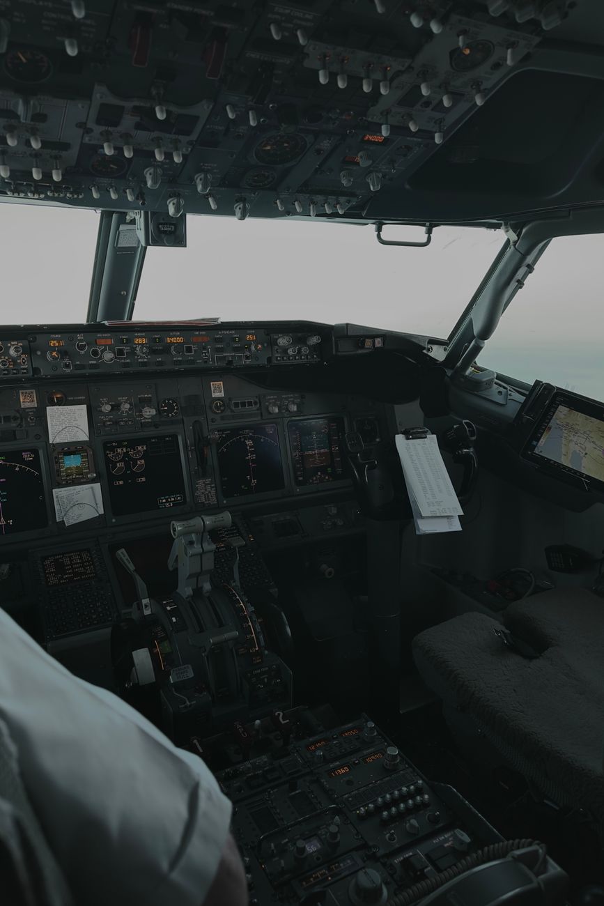
In one Boeing 737 case, an EICAS message indicated “TE FLAP ASYM”, and the flaps stopped at two degrees. Investigation found damage to the number 7 skew harness at connector D8970. The harness was repaired in accordance with standard procedures, after which system checks were normal. Although the fault was reported as a connector issue, the wider lesson is that the connector and its attached harness must be assessed as one mechanical and electrical assembly.
Look for movement-sensitive defects
If an intermittent fault cannot be reproduced during a normal test, determine whether physical movement affects the circuit. Perform manipulation or vibration checks only when approved, and never apply force that could create additional damage.
Pay particular attention to:
- Harnesses near hinges or flight control mechanisms
- Wiring passing through structure
- Clamps and support points
- Areas close to hydraulic, fuel or pneumatic lines
- Engine nacelles and pylons
- Landing gear bays
- Wheel wells
- Avionics racks
- Wiring near heat sources
- Locations where temporary equipment or tools may have contacted the harness
Inspect for chafing, flattened sections, sharp bends, missing clamps, incorrect separation and contact with structure. A conductor can be broken internally while the insulation remains intact. Similarly, insulation damage may create a short only when the harness moves.
If movement causes the fault to appear, isolate the smallest possible section before disturbing the harness further. Document the original routing and support arrangement so that the repair does not introduce a new problem.
Consider environmental conditions
Temperature
Temperature changes can cause materials to expand and contract at different rates. A marginal connector, cracked solder joint or damaged conductor may open when cold and close when warm, or behave in the opposite way.
Moisture and fluid ingress
Humidity, condensation and fluid contamination can reduce insulation resistance and promote corrosion. Inspect for water paths, leaking seals, blocked drains and contamination from hydraulic fluid, fuel, oil or cleaning agents.
Vibration
Vibration can expose loose contacts, broken conductor strands and inadequate harness support. If a fault is associated with engine operation or a particular aircraft configuration, vibration should be considered part of the fault pattern.
Heat
High temperatures can accelerate insulation ageing and damage connectors or splices. Check whether the affected wiring is routed too close to bleed-air ducts, engines, resistors, lights or other heat-producing equipment.
SKYbrary's EWIS reference provides useful safety context on wiring-related hazards, but it does not replace the aircraft manufacturer's maintenance instructions.
Test more than continuity
A continuity test confirms only that a circuit is complete at the time of the test. It may not reveal a high-resistance connection, insulation breakdown or a fault that appears under load.
Depending on the approved procedure, additional checks may include:
- Voltage drop across a connection
- Insulation resistance
- Resistance to structure or shield
- Short-to-ground and short-to-other-wire checks
- Signal quality and amplitude
- Shield and bonding continuity
- Contact retention
- Circuit operation under electrical load
- Data bus or discrete-signal monitoring
A high-resistance fault can be particularly difficult to find. The circuit may show continuity with no load, but the voltage may fall outside limits when current flows. Measuring at both ends of the circuit under the correct load can help distinguish a wiring defect from a faulty component.
Do not overlook grounds and bonding
Ground faults can create symptoms in several systems at once. A weak ground or bonding connection may cause unstable indications, nuisance fault messages or apparent failures of multiple components.
Inspect and test:
- Ground terminals
- Bonding jumpers
- Ground studs
- Fasteners and washers
- Corrosion beneath terminals
- Shield terminations
- Ground wires near high-vibration areas
The reported fault may appear to involve a sensor or computer, while the actual defect is a shared ground or return path.
Interpret changing fault codes carefully
A changing fault code is useful evidence. It can show that a fault is moving through the system or that the monitoring computer is detecting different consequences of the same wiring defect.
For example, a maintenance record may show an engine fault code for a T25 signal disagreement that was initially short-term, followed by a persistent fault with a different code on subsequent flight legs. The aircraft was grounded and an approved alternate deactivation procedure was accomplished. This sequence should prompt a review of the complete circuit, including the sensor, connector, harness and computer input, rather than repeated replacement of the indicated component.
Always interpret fault codes using the aircraft manufacturer's troubleshooting documentation. A code identifies what the system detected, not necessarily the failed part.
Use fault history to improve maintenance decisions
Intermittent wiring faults can have a significant operational cost. A review of FAA data for five major airlines examined the scope of EWIS problems in the United States commercial airline fleet. In the data set, 159 EWIS failures caused groundings or emergency landings. Assuming that each aircraft requires at least one day of maintenance to troubleshoot the fault, these events represent a minimum of approximately $3 million in idle equipment each year.
The same data set included 40 emergency landings, diversions and aborted take-offs. If other airlines experience broadly similar EWIS-related emergency failure rates, this could correspond to approximately 70 incidents annually across a wider fleet.
These figures are estimates based on the stated assumptions, but they demonstrate why troubleshooting accuracy matters. Directing maintenance to the correct location can reduce unnecessary component changes, shorten aircraft downtime and help prevent a fault from becoming a grounding or an in-service event.
Lectromec's analysis of the referenced 2016 data suggested that approximately 5% of EWIS failures resulted in an emergency landing, diversion or aborted take-off. The operational consequences of a small wiring defect can therefore be disproportionate to the size of the defect itself. The FAA's official EWIS guidance offers further regulatory and safety context.
Repair the cause, not only the symptom
Once the fault location has been confirmed, complete the repair using approved procedures and materials. Pay attention to:
- Correct wire type and size
- Approved splices and terminals
- Proper stripping and crimping
- Environmental sealing
- Harness support and separation
- Bend radius
- Shield termination
- Connector assembly
- Chafe protection
- Electrical bonding
- Post-repair testing
A replacement wire or connector will not provide a lasting solution if the harness remains incorrectly routed, unsupported or exposed to heat, fluid or vibration.
After the repair, repeat the relevant operational and system tests. Where possible, verify the aircraft under the conditions associated with the original fault. Record the defect, root cause, repair and test results clearly so that future maintenance teams can identify recurring problems.
Use proactive EWIS inspections
Troubleshooting should not begin only after an aircraft experiences a failure. As aircraft age and electrical systems become more complex, the electrical wiring interconnection system (EWIS) supports an increasing number of flight, propulsion, control and monitoring functions.
A proactive programme can include:
- Targeted inspections of high-risk wiring zones
- Review of repeated fault messages
- Trend analysis of connector and harness defects
- Inspection after major maintenance activity
- Verification of clamp placement and separation
- Checks for fluid contamination and heat damage
- Enhanced inspections on ageing aircraft
- Training in wiring repair and human-factor risks
The fatal accidents involving TWA Flight 800 in 1996 and Swissair Flight 111 in 1998 highlighted the potentially severe consequences of aircraft wiring failures. Modern aircraft incorporate improved protection and monitoring, but the need for sound installation, inspection and maintenance remains. For broader continuing-airworthiness information, consult the EASA continuing-airworthiness resources.
A practical troubleshooting sequence
A disciplined sequence is as follows:
- Record the exact fault and aircraft conditions.
- Review fault history and previous maintenance.
- Consult approved wiring diagrams and fault-isolation data.
- Confirm power, grounds and circuit protection.
- Divide the system into source, wiring, connector and receiver sections.
- Inspect connectors, splices, clamps and harness routing.
- Check for chafing, heat, moisture, corrosion and fluid contamination.
- Use approved electrical tests under the correct load and conditions.
- Investigate movement-, temperature- and vibration-sensitive behaviour.
- Repair the confirmed cause and restore the original protection and routing.
- Repeat functional tests and document the result.
- Look for related or recurring defects elsewhere in the aircraft.
Intermittent electrical faults require patience, accurate records and a willingness to investigate the wiring rather than immediately replacing a computer or sensor. A circuit that works during a simple bench or continuity test may still be unreliable in the aircraft environment.
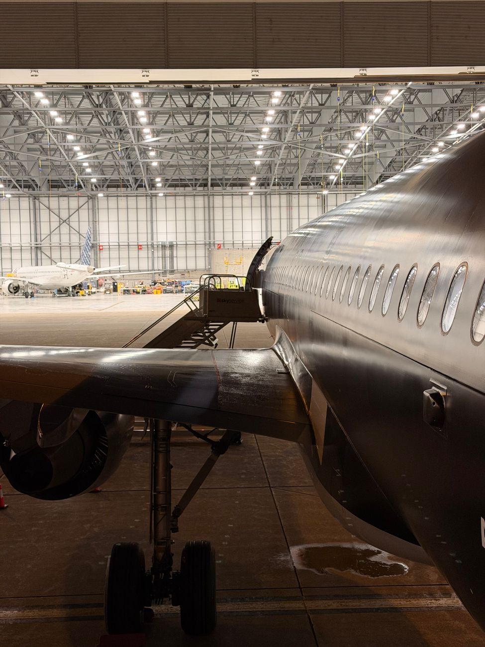
By combining fault history, system knowledge, careful inspection and condition-based testing, maintenance teams can locate hidden EWIS defects more efficiently. This helps keep aircraft serviceable, reduces avoidable downtime and prevents electrical wiring problems from becoming operational emergencies.
Accurate maintenance records support future troubleshooting and licence applications. If your work involves UK Part 66 experience, you can analyse your Part 66 logbook to review and organise your recorded experience.




Login or register to join the conversation.
Join the discussion
0 comments