


.jpg)
If you’re a licensed aircraft engineer, mechanic, or avionics technician, create your free AeroTechCareers profile to showcase your competencies and be found by recruiters actively searching for engineers like you.
Part-66 B2 Module 14 explained: propulsion knowledge for avionics engineers
You may have chosen the B2 route because aircraft electronics, communications, navigation and flight-deck technology interest you. The Part-66 syllabus still requires knowledge of turbine engines, combustion chambers, fuel metering and propellers.
You are not being trained to become a full-time engine mechanic. However, as a B2 engineer, you must understand how propulsion systems work, how they are controlled electronically, and how engine faults affect the aircraft's electrical, indication and warning systems.
That is the purpose of Part-66 Module 14: Propulsion. Before planning your revision, check the latest EASA Part-66 guidance and the requirements published by the relevant national aviation authority.
What is Part-66 Module 14?
Module 14 covers the principles and systems behind aircraft propulsion. It includes the main engine types used in aviation, their construction, fuel and lubrication systems, engine control, and the way propulsion integrates with aircraft systems.
For a B2 engineer, the most relevant areas include:
- Electronic engine-control systems
- FADEC and EEC architecture
- Engine data acquisition and indication
- Overspeed and fault protection
- Engine warning and monitoring systems
- Electrical supplies to engine-control units
- Sensor inputs and signal processing
- Interfaces between the engine, cockpit and aircraft systems
Module 14 helps you understand what the engine is doing and how the aircraft knows what it is doing.
You may not remove a turbine blade during routine avionics maintenance, but you could troubleshoot an engine-indication fault, check a data bus between an EEC and an avionics computer, or investigate why a thrust-control system has rejected a sensor input. For related B2 revision, see our Part-66 Module 13 study guide.
The Module 14 syllabus
The syllabus is broader than many B2 candidates expect. It covers several propulsion types, together with the mechanical principles and electronic controls required for safe operation.
14.1 Turbine engines
The turbine-engine section covers the main propulsion configurations:
- Turbojet engines
- Turbofan engines
- Turboshaft engines
- Turboprop engines
You should understand the basic gas flow through a turbine engine:
- Air enters through the intake.
- The compressor raises its pressure.
- Fuel is introduced and burned in the combustion section.
- Expanding gases drive the turbine.
- The remaining energy produces thrust or shaft power.
The way this energy is used differs between engine types. The SKYbrary turbine-engine reference provides useful supporting background on turbine propulsion concepts.
Turbojet
A turbojet produces most of its thrust from the high-speed exhaust gas leaving the engine. It is relatively simple in concept, but generally less efficient at the subsonic speeds used by most modern transport aircraft.
Turbofan
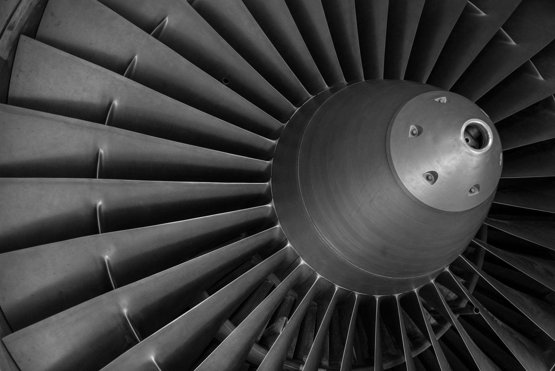
A turbofan uses a large fan at the front of the engine. Some air passes through the core, while the remainder bypasses it. The bypass airflow contributes significantly to thrust and improves fuel efficiency and noise performance.

When studying turbofans, pay attention to:
- Bypass ratio
- Core airflow
- Fan speed
- Compressor and turbine spools
- Exhaust-gas temperature
- Thrust management
These parameters are commonly measured, processed, displayed or monitored by electronic systems.
Turboshaft
A turboshaft engine delivers power through a shaft rather than relying primarily on jet thrust. Helicopter engines are a familiar example.
The engine drives a transmission system, which then powers the rotor. For a B2 engineer, this creates important interfaces involving:
- Torque measurement
- Rotor-speed indication
- Engine-speed indication
- Electronic engine control
- Overspeed protection
- Health and usage monitoring
Turboprop
A turboprop engine drives a propeller through a reduction gearbox. Most of the engine's useful power is delivered through the propeller rather than the exhaust.
Turboprop systems may include electronic propeller control, torque indication, propeller-speed governing and automatic feathering. These systems combine propulsion, control and avionics knowledge, making Module 14 particularly relevant to B2 engineers.
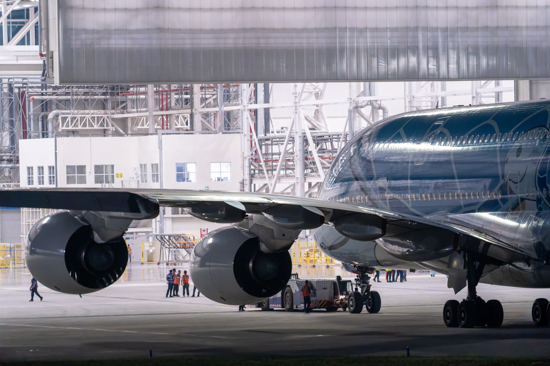
Auxiliary power units
Auxiliary power units, or APUs, are included in the syllabus updates associated with 2023/989.
An APU is a small engine that supplies aircraft systems with services such as:
- Electrical power
- Pneumatic or bleed air
- Engine-starting assistance
- Air-conditioning support while on the ground
Although an APU does not normally propel the aircraft, it remains a propulsion-system topic. Modern APUs rely heavily on electronic control and monitoring, so B2 engineers need to understand:
- APU start sequences
- Speed monitoring
- Exhaust-gas temperature monitoring
- Fuel control
- Generator integration
- Automatic shutdown logic
- Fire and overtemperature protection
- APU fault and maintenance indications
The APU demonstrates why propulsion knowledge matters to avionics personnel. A start fault may involve the fuel system, but it may also involve a starter relay, speed sensor, EGT thermocouple, control unit, wiring harness or aircraft data bus. For a practical example of APU troubleshooting, read our AOG Diaries: APU Failure.
Piston engines and electric or hybrid propulsion
Module 14 also includes piston engines and newer propulsion concepts.
Piston-engine knowledge includes the basic operation of:
- Cylinders and pistons
- Crankshafts
- Connecting rods
- Spark ignition
- Mixture control
- Carburettors or fuel injection
- Cooling and lubrication
- Magneto systems
For B2 candidates, the electrical and control aspects are particularly important. Engine monitoring may include cylinder-head temperature, exhaust-gas temperature, oil pressure, oil temperature and engine speed.
The syllabus also recognises electric and hybrid propulsion. These systems introduce different engineering considerations, including:
- Electric motors
- Power electronics
- High-voltage distribution
- Battery-management systems
- Inverters and converters
- Thermal management
- Isolation monitoring
- State-of-charge and state-of-health monitoring
The underlying technology is changing, but the B2 role remains familiar: understand the sensors, control units, power supplies, warnings, indications and system interfaces.
Engine construction, lubrication and fuel systems
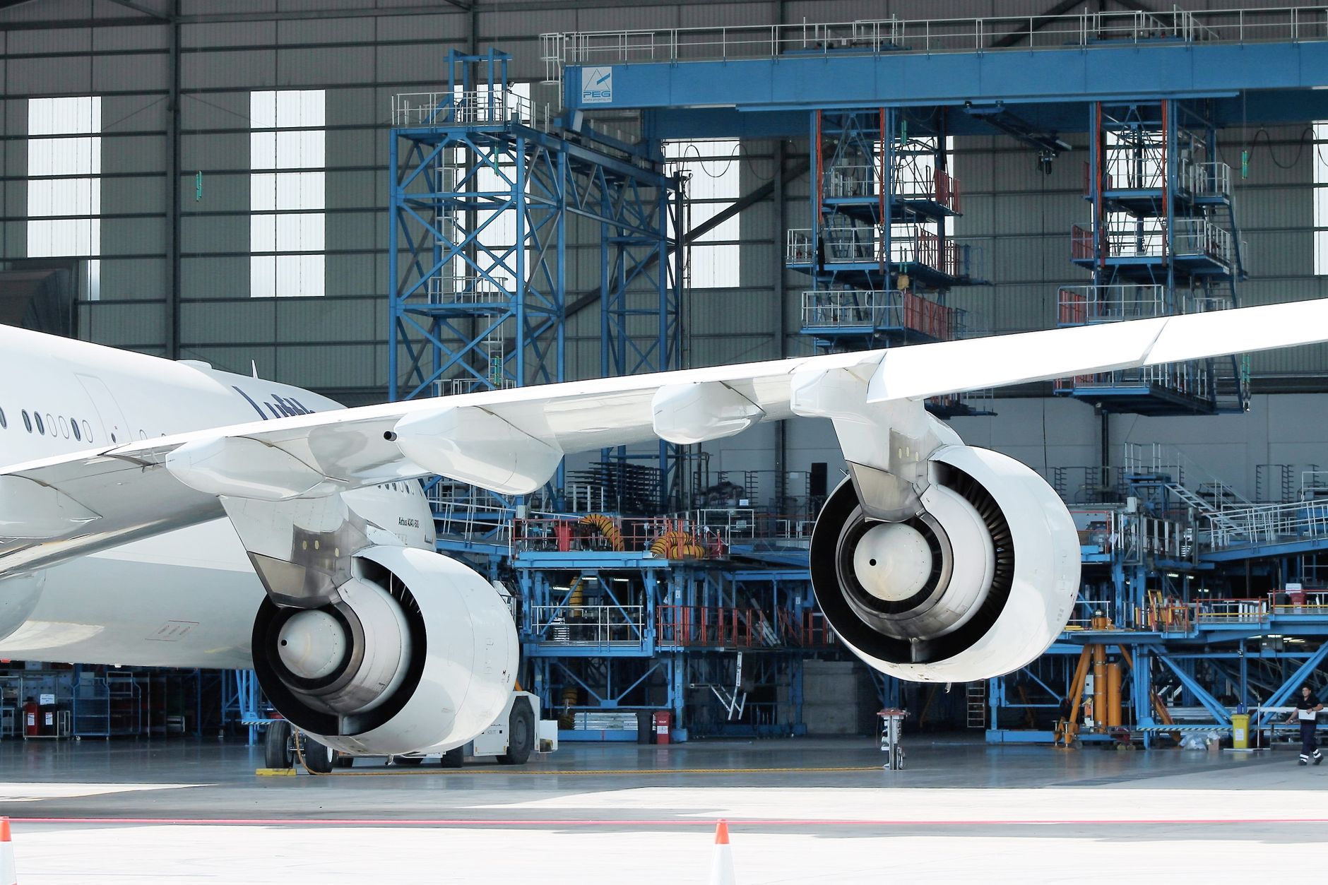
Module 14 is not limited to engine types. You must also understand the major systems that allow an engine to operate safely.
Constructional arrangement
You should be familiar with the general arrangement of:
- Intakes
- Compressors
- Combustion chambers
- Turbine sections
- Exhaust systems
- Shafts and bearings
- Gearboxes
- Propellers and reduction drives
- Engine accessories
The objective is not to memorise every component of a particular engine model. It is to understand the function of each section and how a fault in one area can affect engine indications or control logic.
Lubrication systems
Lubrication systems reduce friction, remove heat and protect bearings and gears. Topics include:
- Oil tanks and sumps
- Pumps
- Filters
- Oil coolers
- Pressure regulation
- Chip detectors
- Oil-pressure and oil-temperature sensing
A B2 engineer may encounter these systems through cockpit indications, electronic monitoring, warning logic or engine health data. An oil-pressure indication problem could be caused by low pressure, but it could also result from a failed transducer, wiring fault, incorrect reference supply or processing-unit problem.
Fuel systems
Fuel systems deliver the correct quantity of fuel to the engine under changing operating conditions. You should understand:
- Fuel pumps
- Filters
- Fuel heaters
- Fuel-control units
- Fuel metering
- Nozzles or injectors
- Shut-off valves
- Fuel-pressure measurement
- Fuel-temperature measurement
Fuel-system knowledge is particularly important when studying engine control. The control system must schedule fuel accurately during starting, acceleration, steady operation, deceleration and shutdown.
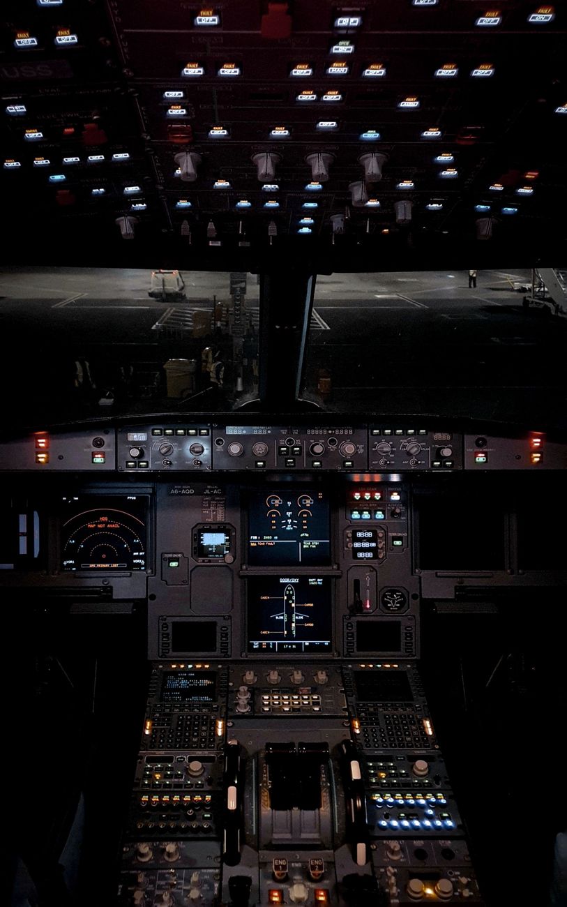
Engine control: the most B2-relevant part of Module 14
For many avionics engineers, engine control is the section where Module 14 becomes most directly relevant.
FADEC
Full Authority Digital Engine Control, or FADEC, is a digital system that controls engine operation across the flight envelope.
Depending on the aircraft and engine design, a FADEC may control or calculate:
- Fuel flow
- Engine acceleration
- Variable stator vanes
- Bleed valves
- Variable exhaust components
- Starting sequences
- Idle speed
- Overspeed protection
- Thrust management
- Engine limits
- Automatic shutdown functions
A FADEC receives inputs from multiple sensors, processes them through control laws and commands actuators. It may also transmit engine parameters to aircraft systems for display, recording, maintenance and performance monitoring.
The B2 engineer should understand the principle of closed-loop control:
- Sensors measure engine conditions.
- The electronic controller compares those conditions with target values or limits.
- The controller commands an actuator.
- The resulting engine response is measured again.
- Fault monitoring checks whether the response is plausible.
EEC and supervisory EEC
An Electronic Engine Controller, or EEC, performs electronic control and monitoring functions for the engine.
Some systems also include a Supervisory EEC arrangement. In such systems, the supervisory controller may calculate or manage higher-level engine functions, while another controller carries out specific control functions or interfaces with the aircraft.
The exact architecture varies, but examination questions may focus on:
- Controller roles
- Input and output signals
- Power supplies
- Channel redundancy
- Data communication
- Control-law monitoring
- Reversion modes
- Fault accommodation
Do not assume that an EEC is simply an avionics computer mounted on the engine. It operates in a harsh environment and is closely integrated with mechanical and hydromechanical systems.

Hydromechanical fuel control
Even on electronically controlled engines, hydromechanical fuel-control elements may remain important.
A hydromechanical system can provide fuel metering and scheduling using mechanical forces such as:
- Fuel pressure
- Engine speed
- Compressor pressure
- Throttle position
- Acceleration or deceleration conditions
Electronic control may command or supervise the hydromechanical unit, while the mechanical system provides a reliable means of regulating fuel flow.
You should understand the difference between:
- Fuel metering: controlling how much fuel is delivered
- Fuel scheduling: determining the appropriate fuel flow for a given operating condition
- Fuel shut-off: stopping fuel delivery during shutdown or a protective action
Redundancy, fault detection and trend monitoring
Engine-control systems must continue to operate safely when a component or signal fails. This is why Module 14 includes redundancy and fault-monitoring principles.
Redundancy
FADEC and EEC systems may use:
- Dual control channels
- Independent power supplies
- Multiple sensors
- Cross-channel comparison
- Separate input and output paths
- Automatic channel selection
Redundancy is not simply a matter of having two identical computers. The system must also detect disagreement, isolate failures and select an appropriate operating mode.
Fault detection
Engine controllers may monitor for:
- Open circuits
- Short circuits
- Out-of-range signals
- Implausible combinations of parameters
- Excessive rates of change
- Loss of communication
- Controller disagreement
- Actuator non-response
A sensor can fail in a way that is electrically detectable, or it can provide a valid-looking but incorrect value. This is why control systems often use signal comparison and plausibility checks.
For example, an engine-speed signal may be compared with another speed signal, fuel flow, compressor pressure and acceleration rate. If the values do not agree, the system can generate a fault or revert to a safer control mode.
Trend monitoring
Trend monitoring examines engine parameters over time rather than considering each reading in isolation.
Typical parameters include:
- Exhaust-gas temperature
- Fuel flow
- Oil pressure
- Oil temperature
- Vibration
- Engine speed
- Torque
- Compressor pressure
- Turbine performance
A gradual increase in exhaust-gas temperature for a given thrust setting, for example, may indicate deterioration before an immediate limit exceedance occurs.
For B2 engineers, trend monitoring may involve data concentrators, aircraft condition-monitoring systems, maintenance computers, data buses and recorded fault messages.
A Module 14 exam-style question
What percentage of the air passing through the combustion section is burned?
- A: 40%
- B: 50%
- C: 75%
Answer: A, 40%.
Only roughly the primary-zone fraction of combustion-section airflow mixes with fuel and burns. The remaining air is secondary and dilution air. It helps complete combustion, cool the flame-tube walls and reduce the gas temperature before the turbine inlet.
This illustrates the level of understanding expected in Module 14. You need to know not only that combustion occurs, but also how airflow is managed to protect the engine and control turbine-entry temperature.
Another engine-control question
In an overspeed-protection circuit, what happens when the current decreases and switches off an overspeed relay?
- A: Increasing current switches off an overspeed relay
- B: Decreasing current switches off an overspeed relay
- C: A centrifugal switch acts like an overspeed relay
Answer: B, decreasing current switches off an overspeed relay.
The question tests your understanding of fail-safe relay logic. In many protection circuits, current holds the relay in its normal state. If the current decreases because an overspeed condition or circuit fault is detected, the relay drops out and initiates the required protective action.
Always study the exact system description in the relevant training material, because aircraft designs differ. The examination objective is to understand the control principle, protection logic and consequences of a failure.
How Module 14 connects with other Part-66 modules
Module 14 does not stand alone. It draws on knowledge from several other areas, including:
- Module 2: Physics, including pressure, temperature and gas-flow principles
- Module 6: Materials and hardware
- Module 7: Maintenance practices
- Module 12: Helicopter aerodynamics, structures and systems, where applicable
- Module 15: Gas turbine engine knowledge
The exact credit and knowledge requirements depend on the licence category, aircraft group and extension route. Always compare the current UK CAA maintenance-licensing requirements with the applicable syllabus and complete a proper gap analysis.
Extending a B2 licence to a B1 category
A B2 holder extending to a mechanical category may receive credit for some common knowledge, but additional examinations or training may still be required.
For example, the published requirements for a B2 holder extending to B1.1 identify topics from:
- Module 2
- Module 6
- Module 7
- Module 11A
A B2 holder extending to B1.4 has a similar requirement, with the relevant helicopter-related modules and subjects specified by the applicable syllabus.
The requirements are published in a straightforward format, with an “X” identifying a required module or topic. Where commonality exists, refer to the syllabus and knowledge level before deciding what you need to study. This is the basis of a proper gap analysis. Do not assume that an existing B2 pass covers every propulsion or mechanical subject.
If the CAA or a UK Part-147 maintenance-training organisation is not available for the relevant assessment or training route, the full module at the required level may need to be completed. Check the current regulatory guidance before booking examinations. You can also use our Part 147 training-school resource to explore approved training options.
Also pay close attention to Modules 7A, 7B, 9A, 9B, 11A, 11B, 11C, 17A and 17B. The notes in the title block explain their applicability and should not be overlooked.
How to study Module 14 as a B2 candidate
The most effective approach is to connect every propulsion topic to an avionics function.
When studying a fuel system, ask:
- Which sensors measure fuel pressure or temperature?
- How is fuel flow indicated?
- Which computer processes the signal?
- What happens if the sensor fails?
- Is the system analogue, discrete or data-bus based?
When studying a turbine engine, ask:
- Which parameters are monitored?
- How are engine limits calculated?
- How does the aircraft display engine information?
- Which protections operate automatically?
- What maintenance messages are generated?
When studying FADEC, concentrate on:
- Inputs
- Outputs
- Control loops
- Redundancy
- Power supplies
- Failure detection
- Reversion modes
- Interfaces with the aircraft
Diagrams are particularly useful. Draw the relationship between the sensor, controller, actuator, aircraft computer, cockpit display and maintenance system. This turns a long list of propulsion terminology into a system that you can reason through.

For wider revision advice, review our guide to Part-66 exam rules, pass marks and resits.
The takeaway
Module 14 may appear to be a mechanical-engine topic, but much of its content is directly relevant to B2 work.
You need enough propulsion theory to interpret engine parameters, troubleshoot electronic control systems, follow wiring and signal paths, and recognise how faults affect aircraft operation.
Focus on the relationship between the engine and its control system:
- The engine produces power.
- Sensors measure its condition.
- The EEC or FADEC processes the information.
- Actuators control fuel and engine operation.
- Aircraft systems display, record and monitor the results.
- Redundancy and fault detection support safe operation.
That is the B2 perspective on propulsion. You may not rebuild the engine, but you must understand how its electronic control system works and how to prove that it is working correctly.




Login or register to join the conversation.
Join the discussion
0 comments